fio versions < 3.3 may show inflated random write performance

TL;DR

If your storage system implements inline compression, performance results with small IO size random writes with time_based and runtime may be inflated with fio versions < 3.3 due to fio generating unexpectedly compressible data when using fio’s default data pattern. Although unintuitive, performance can often be increased by enabling compression especially if the bottleneck is on the storage media, replication or a combination of both.

fio 2.8.1 vs fio 3.33 data patterns

Therefore if you are comparing performance results generated using fio version < 3.3 and fio >=3.3 the random write performance on the same storage platform my appear reduced with more recent fio versions.

fio-3.3 was released in December 2017 but older fio versions are still in use particularly on distributions with long term (LTS) support. For instance Ubuntu 16, which is supported until 2026 ships with fio-2.2.10

Continue reading

Specifying Drive letters with fio for Windows.

fio on Windows

Download pre-compiled fio binary for Windows

Example fio windows file, single drive

This will create a 1GB file called fiofile on the F:\ Drive in Windows then read the file.  Notice that the specification is “Driveletter” “Backslash” “Colon” “Filename”

In fio terms we are “escaping” the : which fio traditionally uses as a file separator.

[global]
bs=1024k
size=1G
time_based
runtime=30
rw=read
direct=1
iodepth=8

[job1]
filename=F\:fiofile 
Continue reading

Using rwmixread and rate_iops in fio

Creating a mixed read/write workload with fio can be a bit confusing. Assume we want to create a fixed rate workload of 100 IOPS split 70:30 between reads and writes.

Don’t mix rwmixread and rate_iops
TL;DR

Specify the rate directly with rate_iops=<read-rate>,<write-rate> do not try to use rwmixread with rate_iops. For the example above use.

rate_iops=70,30 

Additionally older versions of fio exhibit problems when using rate_poisson with rate_iops . fio version 3.7 that I was using did not exhibit the problem.

Continue reading

Why does my SSD not issue 1MB IO’s?

First things First

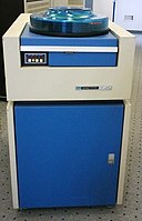
https://commons.wikimedia.org/wiki/File:CDC9762-smd-drive.jpg
CDC 9762 SMD disk drive from 1974

Why do we tend to use 1MB IO sizes for throughput benchmarking?

To achieve the maximum throughput on a storage device, we will usually use a large IO size to maximize the amount of data is transferred per IO request. The idea is to make the ratio of data-transfers to IO requests as large as possible to reduce the CPU overhead of the actual IO request so we can get as close to the device bandwidth as possible. To take advantage of and pre-fetching, and to reduce the need for head movement in rotational devices, a sequential pattern is used.

For historical reasons, many storage testers will use a 1MB IO size for sequential testing. A typical fio command line might look like something this.

fio --name=read --bs=1m --direct=1 --filename=/dev/sda
Continue reading

How to identify SSD types and measure performance.

Thomas Springer / CC0
Generic SSD Internal Layout

The real-world achievable SSD performance will vary depending on factors like IO size, queue depth and even CPU clock speed. It’s useful to know what the SSD is capable of delivering in the actual environment in which it’s used. I always start by looking at the performance claimed by the manufacturer. I use these figures to bound what is achievable. In other words, treat the manufacturer specs as “this device will go no faster than…”.


Identify SSD

Start by identifying the exact SSD type by using lsscsi. Note that the disks we are going to test are connected by ATA transport type, therefore the maximum queue depth that each device will support is 32.

# lsscsi 
[1:0:0:0] cd/dvd QEMU QEMU DVD-ROM 2.5+ /dev/sr0
[2:0:0:0] disk ATA SAMSUNG MZ7LM1T9 404Q /dev/sda
[2:0:1:0] disk ATA SAMSUNG MZ7LM1T9 404Q /dev/sdb
[2:0:2:0] disk ATA SAMSUNG MZ7LM1T9 404Q /dev/sdc
[2:0:3:0] disk ATA SAMSUNG MZ7LM1T9 404Q /dev/

The marketing name for these Samsung SSD’s is “SSD 850 EVO 2.5″ SATA III 1TB

Identify device specs

The spec sheet for this ssd claims the following performance characteristics.

Workload (Max)SpecMeasured
Sequential Read (QD=8)540 MB/s534
Sequential Write (QD=8)520 MB/s515
Read IOPS 4KB (QD=32)98,00080,00
Write IOPS 4KB (QD=32)90,00067,000
Continue reading

Paper: A Nine year study of filesystem and storage benchmarking

A 2007 paper, that still has lots to say on the subject of benchmarking storage and filesystems. Primarily aimed at researchers and developers, but is relevant to anyone about to embark on a benchmarking effort.

  • Use a mix of macro and micro benchmarks
  • Understand what you are testing, cached results are fine – as long as that is what you had intended.

The authors are clear on why benchmarks remain important:

Ideally, users could test performance in their own settings using real work- loads. This transfers the responsibility of benchmarking from author to user. However, this is usually impractical because testing multiple systems is time consuming, especially in that exposing the system to real workloads implies learning how to configure the system properly, possibly migrating data and other settings to the new systems, as well as dealing with their respective bugs.”

We cannot expect end-users  to be experts in benchmarking. It is out duty as experts  to provide the tools (benchmarks) that enable users to make purchasing decisions without requiring years of benchmarking expertise.

Storage Bus Speeds 2018

Storage bus speeds with example storage endpoints.

Bus Lanes End-Point Theoretical Bandwidth (MB/s) Note
SAS-3 1 HBA <-> Single SATA Drive 600 SAS3<->SATA 6Gbit
SAS-3 1 HBA <-> Single SAS Drive 1200 SAS3<->SAS3 12Gbit
SAS-3 4 HBA <-> SAS/SATA Fanout 4800 4 Lane HBA to Breakout (6 SSD)[2]
SAS-3 8 HBA <-> SAS/SATA Fanout 8400 8 Lane HBA to Breakout (12 SSD)[1]
PCIe-3 1 N/A 1000 Single Lane PCIe3
PCIe-3 4 PCIe <-> SAS HBA or NVMe 4000 Enough for Single NVMe
PCIe-3 8 PICe <-> SAS HBA or NVMe 8000 Enough for SAS-3 4 Lanes
PCIe-3 40 PCIe Bus <-> Processor Socket 40000 Xeon Direct conect to PCIe Bus


Notes


All figures here are the theoretical maximums for the busses using rough/easy calculations for bits/s<->bytes/s. Enough to figure out where the throughput bottlenecks are likely to be in a storage system.

  1. SATA devices contain a single SAS/SATA port (connection), and even when they are connected to a SAS3 HBA, the SATA protocol limits each SSD device to ~600MB/s (single port, 6Gbit)
  2. SAS devices may be dual ported (two connections to the device from the HBA(s)) – each with a 12Gbit connection giving a potential bandwidth of 2x12Gbit == 2.4Gbyte/s (roughly) per SSD device.
  3. An NVMe device directly attached to the PCIe bus has access to a bandwidth of 4GB/s by using 4 PCIe lanes – or 8GB/s using 8 PCIe lanes.  On current Xeon processors, a single socket attaches to 40 PCIe lanes directly (see diagram below) for a total bandwidth of 40GB/s per socket.

  • I first started down the road of finally coming to grips with all the different busses and lane types after reading this excellent LSI paper.  I omitted the SAS-2 figures from this article since modern systems use SAS-3 exclusively.

[pdf-embedder url=”https://www.n0derunner.com/wp-content/uploads/2018/04/LSI-SAS-PCI-Bottlenecks.pdf” title=”LSI SAS PCI Bottlenecks”]


Intel Processor & PCI connections


Creating compressible data with fio.

binary-code-507785_1280

Today I used fio to create some compressible data to test on my Nutanix nodes.  I ended up using the following fio params to get what I wanted.


buffer_compress_percentage=50
refill_buffers
buffer_pattern=0xdeadbeef
  • buffer_compress_percentage does what you’d expect and specifies how compressible the data is
  • refill_buffers Is required to make the above compress percentage do what you’d expect in the large.  IOW, I want the entire file to be compressible by the buffer_compress_percentage amount
  • buffer_pattern  This is a big one.  Without setting this pattern, fio will use Null bytes to achieve compressibility, and Nutanix like many other storage vendors will suppress runs of Zero’s and so the data reduction will mostly be from zero suppression rather than from compression.

Much of this is well explained in the README for latest version of fio.

Also NOTE  Older versions of fio do not support many of the fancy data creation flags, but will not alert you to the fact that fio is ignoring them. I spent quite a bit of time wondering why my data was not compressed, until I downloaded and compiled the latest fio.


Cache behavior – How long will it take to fill my cache?

When benchmarking filesystems or storage, we need to understand the caching effects. Most often this involves filling the cache and reaching steady state. But how long will it take to fill a cache of a given size? The answer depends of course on the size of the cache, the IO size and the IO rate. So, to simpify let’s just say that a cache consists of some number of entries. For instance a 4GB cache would have 1 million 4KB entries. In my example this is simply a 1M entry cache.

In terms of time to fill the cache, it’s simpler to think about how many entries will need to be read before the cache is filled.

For a random workload, it will be more than 1M “reads”. Let’s see why.

The first read will be inserted into the cache, the second read will probably be inserted into the cache, but there is a small (1/1000000) chance that the second read will actually be already in the cache since it’s random. As the cache gets fuller – the chances of a given read already being present in cache increases. As a result it will take a lot more than 1 million reads to populate the entire cache with a random read workload.

The question is this. Is is possible to predict, how many “reads” it will take to fill the cahe?

The experiment.

In this experiment, we create an array to represent the cache. It has 1M entries. Then using a random number generator, simulate the workload and measure how long it takes to populate the cahche.

Results

After 1,000,000 “reads” there are 633,000 positive entries (entries that have data in them). So what happened to the other 367,000? The 367,000 represent cache “hits” on an existing entry. Since the read “workload” is 100% random, there is some chance that a subsequent read will be for an entry that is already cached. Over the life of 1,000,000 reads around 37% are for an entry that is already cached.

After 2,0000,000 reads the cache contains 864,000 entries. Another 1,000,000 reads yields 950,000.

The fuller that the cache becomes, the fewer new entries are added. Intuitively this makes sense because as the cache becomes more full, more of the “random reads” are satisfied by an existing cache entry.

In my experiments it takes about 17,000,000 “reads” to ensure that every cache entry is filled in a 1M entry cache. Here are the data for 19 runs.

Cachefullness

Iteration Positive Entries Empty Slots 1 631998 368002 2 864334 135666 3 950184 49816 4 981630 18370 5 993266 6734 6 997577 2423 7 999080 920 8 999660 340 9 999879 121 10 999951 49 11 999985 15 12 999996 4 13 999998 2 14 999998 2 15 999999 1 16 999999 1 17 1000000 0 18 1000000 0
  • For 500,000 Entries it takes 15 iterations to fill all the entries.
  • For 2,000,000 Entries it takes 19 iterations to fill all the entries.

Interestingly, the ratio of positive to empty entries after one iteration is always about 0.632:0.368

  • 0.368 is roughly 1/e
  • .632 is roughly 1-(1/e).

Things to know when using vdbench.

Recently I found that vdbench was not giving me the amount of outstanding IO that I had intended to configure by using the “threads=N” parameter. It turned out that with Linux, most of the filesystems (ext2, ext3 and ext4) do not support concurrent directIO, although they do support directIO. This was a bit of a shock coming from Solaris which had concurrent directIO since 2001.

All the Linux filesystems I tested allow multiple outstanding IO’s if the IO is submitted using asynchronous IO (AKA asyncIO or AIO) but not when using multiple writer threads (except XFS). Unfortunately vdbench does not allow AIO since it tries to be platform agnostic.

fio however does allow either threads or AIO to be used and so that’s what I used in the experiments below.

The column fio QD is the amount of outstanding IO, or Queue Depth that is intended to be passed to the storage device. The column iostat QD is the actual Queue Depth seen by the device. The iostat QD is not “8” because the response time is so low that fio cannot issue the IO’s quickly enough to maintain the intended queue depth.

Device
fio QD
fio QD Type
direct
iostat QD
 ps -efT | grep fio | wc -l
/dev/sd
8
libaio
Yes
7
5
/dev/sd
8
Threads
Yes
7
12
ext2 fs (mke2fs)
8
Threads
Yes
1
12
ext2 fs (mke2fs)
8
libaio
Yes
7
5
ext3 (mkfs -t ext3)
8
Threads
Yes
1
12
ext3 (mkfs -t ext3)
8
libaio
Yes
7
5
ext4 (mkfs -t ext4)
8
Threads
Yes
1
12
ext4 (mkfs -t ext4)
8
libaio
Yes
7
5
xfs (mkfs -t xfs)
8
Threads
Yes
7
12
xfs (mkfs -t xfs)
8
libaio
Yes
7
5

At any rate, all is not lost – using raw devices (/dev/sdX) will give concurrent directIO, as will XFS. These issues are well known by Linux DB guys, and I found interesting articles from Percona and Kevin Closson after I finally figured out what was going on with vdbench.

fio “scripts”

For the “threads” case.

[global]
bs=8k
ioengine=sync
iodepth=8
direct=1
time_based
runtime=60
numjobs=8
size=1800m

[randwrite-threads]
rw=randwrite
filename=/a/file1

For the “aio” case

[global]
bs=8k
ioengine=libaio
iodepth=8
direct=1
time_based
runtime=60
size=1800m


[randwrite-aio]
rw=randwrite
filename=/a/file1